
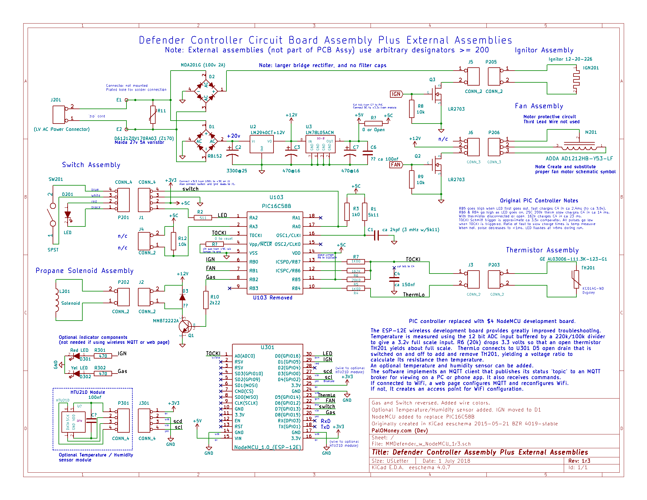
It was the travel day of our two week vacation. Time was getting short before we had to leave to catch our flight. I put full propane tanks on our Defender and Patriot traps, replenished the Octenol attractant, and restarted each trap. I was relieved to see the Patriot start, as it was sometimes balky starting, especially with a newly filled tank in which there is sometimes trapped air requiring bleeding and perhaps several restarts. I was surprised that the Defender didn’t start, but less concerned, as this trap was modified to use a NodeMCU ESP8266 chip with WiFi supporting remote control, so it could be restarted from anywhere in the world having an internet connection.
This Defender was placed in a critical location between a wetland area and the pool. Its job is to intercept mosquitoes before they can attack pool goers. This season, it has caught enough mosquitoes to pack and overflow the catch basket three times. That’s a lot. The Patriot is behind a patio area to catch mosquitoes coming from other locations. The Patriot catches disappointingly few mosquitoes (a few hundred this season so far).
I tried to start the Defender twice before leaving, but was willing to sacrifice the evening’s catch in order to not miss the flight, given that we would have internet after we landed.
I tried to start the trap perhaps 8 times the next day, but the combustion chamber temperature reported by MQTT refused to go up by more than a few degrees Celsius, so each time the trap shut down in a fault condition. In the past, trapped air was generally purged after maybe 4 or 5 starts at the most. I started to wonder. Before I left, I had made sure the tank gas valve was open (after a couple of incidents during the past years). The on/off switch indicated on. There was a reported 3-5°C temperature rise during each start, indicating that at least the igniter wasn’t burned out, and that the fan had blown the hot igniter heat through the catalytic converter to the thermistor probe.
I tried running the igniter during the warm up phase, where it normally would be off. At one point, it ran for 600 seconds (10 minutes), to no improvement. Later attempts failed to yield much or any temperature rise. I had to give up and hope the Patriot would take up the slack.
Day 1
Back home after two weeks, the Defender still didn’t start. The power cord was intermittent, kept falling out. Closed and reopened the gas valve, restarted again, no effect. Later I started charging a spare sealed lead acid battery to run my tire pump for blowing out the nozzle. Could not find the clips to cigarette lighter adapter. Attached the tire pump with clip leads, set the tire pump to max (119) psi, run for a bit, and the leads begin to smoke. Scrounged some heavier duty wiring, tried again. The pressure eventually drops, but so does the compressor speed.
(The “modern” tire pumps use a digital display to set the desired pressure, then, when the pump is turned on from being off, display the pump pressure as it fills the tire. Better for this purpose is the previous generation that has a simple power switch and an analog gauge. The modern pump will not start unless the battery is connected with the switch off, and then the switch turned on, very inconvenient, especially for projects that require automatic pump operation, such as keeping an old, brittle, leaky top ring of an above ground pool inflated.)
I lifted off the case top cover (no screws) and took a look. It was disturbing to notice a dark spot on the controller PCB under the igniter MOSFET. Running a cycle, the igniter remained cold. Disconnecting and taking the Defender “power unit” inside, washing out a (3 overflowing baskets) season’s worth of dead mosquitoes and mosquito parts, and removing the controller PCB assembly, revealed PCB charring around the igniter MOSFET, and heat damage to the adjacent fan connector. The igniter Molex pin connectors were mottled with some yellowish corrosion-looking spots.
Measuring the igniter LR2703 MOSFET showed a defective source to gate junction. Removing the MOSFET caused the drain pad to detach from the charred circuit board (should have used the hot air station). Scraping the board to clean it removed most of the charred material, but the woven layer below was black in color, indicating a chemical change.
The use of the PCB as a heat-sink was in this case inadequate to handle 10 minutes of igniter operation on a hot day, especially given that the gate was driven by a 3.3 volt logic signal from the ESP8266, not 5 volts from the PIC controller. The LR2703 really needs that 5 volts to give a low on resistance, current limiting at 20 A. But at 3.3 volts, that figure is close to only 4 A, and the Rds is about 1.5 ohms instead of about 0.1 Ohms. When hot after 3 seconds, the installed 12 volt silicon nitride igniter resistance is 7.5 to 5.25 Ohms, and draws 1.6 to 2.3 Amps. (When cold, it is about 5 times that, but this is limited by the power supply transformer and line cord, and the MOSFET.)
No spares were on hand. Just as well, as this MOSFET type is unsuitable for 3.3 logic level drive, and the PCB was ruined for use as a heat sink. Searching for a better alternative yielded the TO220 IRLZ24N Power MOSFET, which was ordered (next day!) along with some high temperature silicone adhesive to attach the lifted pad and the TO220.
Day 2
The MOSFET(s) and adhesive arrived the next day, but too late for any work.
Day 3
Attaching the pad with the high temperature silicone adhesive was a complete mess, I wished I had used high temperature epoxy instead. However, the pad could not be used for contact to the TO220 anyway, so the adhesive was used to attach the TO220 on top of the PCB MOSFET location. Because TO220 leads are thick and stiff, the concern was that they would rip up the existing PCB source and gate pads. The leads were carefully attached with a short loop of fine stranded wire that could flex and not put excessive pressure on the pads. The drain was attached directly to the Molex connector pin. The adhesive gave the TO220 some additional flexibility so that temperature variations would not rip the source and gate pads off the circuit board.
The circuit failed bench testing. Examination of the wires connecting the NodeMCU to the original controller board revealed that the red ignition drive wire had come loose from the PCB. This was attached, tested, and the new MOSFET worked. Powering the igniter, the MOSFET got warm, but not too hot, so a heat-sink was not added.
The intake temperature and humidity sensor had not worked all season. There was no obvious sign of of damage or contamination. Fortunately there was a new sealed HTU21 module, to which a connector was added. The sensor was connected, and the trap displayed valid temperature and humidity. No idea why the old one failed, it is marked and saved for “future investigation.”
The battery and tire pump were brought inside, connected, and the pressure measured at 98 psi, a high value, but this inaccurate measurement is not comparable to previous measurements using an older style analog pump.
I disassembled the trap, cracked the case, and cleaned the nozzle first in mineral spirits, then in brake cleaner in a plastic cup in an ultrasonic cleaner for 30 minutes. Reassembling the nozzle, I saw something that looked like plastic in the ring around the nozzle. I don’t know how these work, but guessing that the propane comes out of that ring, picked the white material (from the plastic container?) from the ring. The nozzle was reinstalled in the combustion chamber. Having long ago decided that the existing adhesive seemed to be sufficient, no adhesive was removed or newly applied.
Connected an auto tire air compressor set to 119 psi, and blew air through the nozzle. Apparently the pump has been damaged as it displayed only 888 and not the nozzle air pressure – another project.
The three Richco PCB standoffs were in bad shape, so they were replaced. I had purchased a bag of 100, so why not? Not so fast! Remnants of the old standoffs were stuck in the case, requiring a drill to clean out. Regrettably, the drill apparently damaged a second thread (the first was damaged years earlier, some people never learn), and two of the clips aren’t tight when threaded into the case. But they don’t fall out!
Heat damage to the fan connector was cleaned up, but the fan failed to start. This new fan issue was treated by extracting, with great effort, pins 1 and 3 of the female Molex connector, then cleaning and re-bending them to make tighter contact. (Too bad pin 2 was not treated, as it is the active pin, not pin 3!) The fan worked better, but was not perfect. There was a not fully inserted position in which it worked, so it was left partially inserted, therefore intermittent, deferring a complete repair to “the future.”
The trap was reassembled, deployed, and started. Of course it didn’t work. But at least the trap was back to where it was before I smoked the LR2703 from afar.
Was the ignition somehow degraded? Applied DeOxit to the AC connector terminals. No effect. Rain started to fall. Inside I made a list of possible issues: 1) power supply “weak” (many players here), 2) nitride igniter defective, not hot enough (and no new spares!), 3) Nozzle still obstructing (but just cleaned!), and 4) No gas flow (but the gas valve clicks!).
Day 4
Swapped power supplies (transformer and low voltage line cord). No change.
In the past, there had been examples of igniters that get hot connected to a battery, but don’t work in the trap. The Mosquito Magnet spare parts bag includes 6 igniters: 1 original open circuit, 1 open circuit silicon nitride, and 4 silicon nitride igniters that somehow stopped working and were replaced by new ones. That’s a lot of partially failed igniters, especially given that these are supposedly more robust than the originals. Two new silicon nitride igniters were ordered from different sellers (as if that would matter). Delivery times were on the order of 2+ days.
In the meantime. The igniters were measured using a hand held infrared temperature probe designed for areas larger than the small tip of an igniter. Temperatures indicated from 323-392°C, way too low. Propane’s ignition temperature in air is 493–604ºC. Igniters run much hotter, 1180-1330°C. The igniters were connected to a 12V sealed lead acid battery, and they glowed hot enough (but not white hot) to ignite propane from a torch (but the flame went out as the torch was removed from the igniter, why is that?).
Other time was spent inventorying the other spare parts. There were lots of nozzles, including expensive 6 WDA (water use) nozzles, at one time mistakenly believed to be correct replacements for the trap.
I really wanted to run the trap to catch some mosquitoes. For this, manual lighting would be OK. I tried lighting the trap twice using a wooden kitchen match, but this is nearly impossible as the wind from the fan just blows the match out before it can be inserted into the combustion chamber.
Day 5
The first new igniter arrived, was tested with results similar to the others above. The igniter was deployed, and the trap didn’t start, just exhibiting the normal 3-4°C temperature rise. Bench tested the removed igniter. It performed nearly identically to the new one.
Was it the new MOSFET, the power supply, or the full-wave bridge rectifier? The igniter connector was disconnected and placed outside the case, an adapter wired, and the battery was used to power the igniter during a cycle. The trap still didn’t start.
It had to be the gas. The original regulator had failed a few years back, causing strange combustion behavior. The new regulator was the same as that now on my much newer Patriot, only even yet newer. Was it the nozzle?
Day 6
The spare parts did have a new nozzle, never used. The case was cracked, the nozzle installed, the trap assembled, and cycled but I forget to open the propane valve. After a while, I realized this and tried again. Still nothing. The trap didn’t start. Getting tired of this.
Was it the tank or the regulator? I remembered there was no “pop” when removing the regulator from the tank like when removing a full tank from a trap. Switching tanks with the working Patriot, the trap was cycled, but didn’t start.
Day 7
Was there any gas flow? Finding the remains of the hand made pressure test fixture that screwed into the Schrader valve, the BMP180 pressure sensor having been fried by mis-wiring on another project and removed, leaving an open slit in the plastic bottle. The fixture was screwed into the Schrader valve, allowing any propane to escape, and the trap started. There was no hint of propane from the bottle, and a spark failed to detect any propane. No gas flow!
What about the “gas reset tool?” This was located and tried, but did not fit either Defender or Patriot regulators, which have a much smaller center hole for some purpose.
This leaves the regulator and valve. I had another regulator from the regulator bake off a few years ago, and a spare valve assembly used for nozzle pressure testing. Taking the spare apart revealed that it was missing the internal plunger and spring. If the valve were defective, the plunger could be bypassed by opening the valve and covering the stopper part with wide package sealing tape. The regulator output pressure of 11 inches water column is quite low, so the tape could temporarily contain the gas. This obviously unsafe practice is not recommended.
While contemplating unscrewing the regulator, a weary snap decision was made to bypass the valve instead. A T10 screwdriver removed the actuator, the parts not lost in the yard (amazing!), and ordinary clear sealing tape (unrated for sealing propane valves, so not recommended) applied. 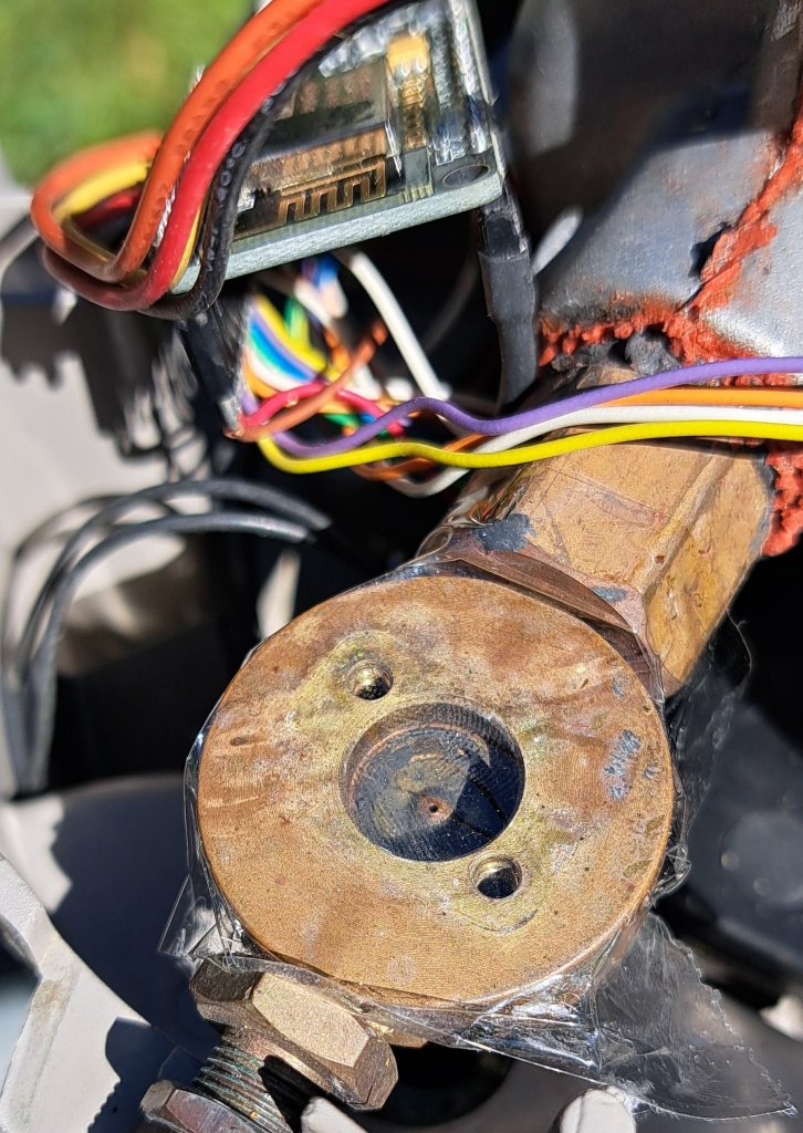 The trap was started, and in due time the satisfying ignition pop was heard. Success!
But then smoke started pouring out of the exhaust port. What was this? Not really concerned about fire in the combustion chamber, I wondered as to its cause. Was the trap started so many times that something built up inside like a car that doesn’t start then backfires? How could that be given that there had been no gas flow? Was some contaminant added to the combustion chamber? Some unlucky insect (but no organic burning odor)? Loose adhesive sealant? What? It took several minutes for the smoke to stop.
The smoke stopped, but then the combustion chamber temperature kept rising. Normally, this Defender runs at about a 92°C temperature rise above ambient. At 23°C, that would be 115°, maybe 120°. The NodeMCU high temperature cutoff had been set to 140°C, and the trap was getting close to that. The command to set the limit to 150°C came too late, and the machine entered an over-temperature state, the software shutting off the gas until cooled, then fan off, and fault indication. But the valve was bypassed, so the gas stayed on! Manually closing the tank gas valve started the cooling. It took a surprisingly long time to get to a reasonable temperature. The high temperature cutoff was set to 160°C, the gas valve opened, and the trap restarted, and the temperature again took off.
After 3 hours operation the trap was still at 146°C (see MQTT Legend below):
Temp=145.9C (0) at 5:13655 F=1 I=0 G=1 S=1 E=0 T=23.4C H=50.4% M=26584 (142/1024:3031) R=70~160 W=-81.85 B=0.0 V=3.5
I have no explanation for this hot running mode. It remains to be seen if this trap catches any mosquitoes.
Day 8
Check the Defender, running:
Temp=148.3C (0) at 5:66690 F=1 I=0 G=1 S=1 E=0 T=27.1C H=48.5% M=26568 (135/1024:2858) R=70~160 W=-82.85 B=0.0 V=3.5
Shut down to remove the tape and install the valve actuator without losing the actuator or damaging the very thin O ring. Start the trap. Fan does not operate. Notice that the power connection is intermittent, then no fan even with power. Multiple system failures. Remove the power head and take it to the lab.
Printed the schematic and troubleshot the 12V supply and connections, hard to do with conformal coating preventing probing. Soldered foil side pads to burn through the acrylic to get a test connection, 12V measured 12V. But still no fan, although the NodeMCU drive pin was high. Removed the PCB from combustion chamber, and discovered that the blue fan wire was disconnected from the PCB via that connects the original PIC controller to the Fan MOSFET, the second broken wire this round. Unplugged all connectors, and reconnected the wire. Then, in a fit of pique, used acrylic glue to attach that wire plus the red ignition lead to the PCB for strain relief. (Click the 2019 before picture twice for a closeup, and to get an idea of the workmanship described here.) The other wires connect to pads or terminals that should withstand some wire movement. The acrylic puddle would take some time to set.
Waiting for the acrylic to set, examined the now completely non-functional attachment points for the AC connector. Decided to rebuild these!
The quick way is to cast new plastic, but all the casting materials had long ago expired, and where were they, anyway? Found some epoxy putty in the basement with no expiration date. Cutting a chunk and mixing it was rather difficult. The material was quite stiff and not sticky. Applied it but then immediately removed it and cleaned up. Considered Shoe Goo, a marvelous material, but decided it would not be rigid enough. This left JB Weld, which takes a day to cure, and several hours to set enough to maintain a shape. Without materials to make a mold or fence to contain a viscous liquid, I mixed the material anyway, here goes!
Initially applied the epoxy to the three chamber mounting posts, which had stripped many tear-downs ago. Applied the rest to the AC connector posts. Working this material took hours. After about 3 hours, it was the consistency of a thick putty, perhaps too thick. I kept working it into a solid around the original posts. Several incidents of dripped epoxy on clothes, the rug, etc., necessitated emergency measures involving alcohol and soap, while the material continued to flow. The most ruined post just would not be reformed until a small twist drill was positioned and the material stuck to that. This formed the basis of a structure to which the flowing material could be attracted. There was clay that may even still be good around somewhere that could have been used to create a form to contain the epoxy, but the clay, although vividly remembered, has not actually been seen in a few years. Anyway, after a few punishing hours, posts were formed, and the whole thing left overnight to cure.
Day 9
Checked the JB Weld, looks solid. Drilled pilot holes, and larger holes in the new posts. Cut threads with screws. Use an end mill to clean up splatter from case, but this made a mess. Used a wire brush to clean that up. Vacuumed and blew out chips and residue. Checked the main chamber support posts. Try a screw in the post by the gas line, hear a crack as it breaks from a horizontal piece, not essential. Drill pilot and tapping holes in this and other posts. Vacuumed and blew out the case bottom. Mounted the combustion chamber assembly using 3 screws, which are solid in the posts for the first time in years. The #2 Philips screwdriver has some difficulty turning the screws. They are all tightened to flush, but not more.
Oops: what about the PCB foil coating exposed for testing? Sprayed acrylic coating for artwork on the PCB circuit side. Dries in 15 minutes. Let sit for an hour.
Mount the dried controller PCB in trap. Oops: forgot to wash some acid flux from the PCB before spraying the acrylic. Oh, well. Scrape the AC connector male contacts with file to remove oxide. Screw the AC connector into the new posts. Solid. A big success.
Test run no gas. MQTT temperature reads -43.7°C or so, a symptom of no thermistor connection. Remove the acrylic from the thermistor male connector, remove the contacts from the female connector to clean, difficult. These are gold plated contacts. Measure the thermistor at 100 kOhms, Ok.
Bring a nearly but not completely empty propane tank to the lab, connect it, and start a run. 10-15°C temperature rise. The valve works. Deploy to the outside location, connected, and started, The trap is working.
The ambient temperature sensor is currently incorrectly positioned above the intake air flow, where it is much hotter from the combustion. This will be adjusted after a day or two of catching mosquitoes.
Day 11
The dreaded offline MQTT message shows up. Go to the Defender, the power connection is intermittent in the sunlight and hot day. Wrap the power cord around the gas line to press the connector into contact. Go to the office and order a contact burnishing tool (plus some quick setting epoxy putty!). Positioned the ambient temperature and humidity sensor to be more in the air intake. Very few if any mosquitos caught so far, perhaps the air temperature is still too hot.
Temp=150.8C (0) at 5:7920 F=1 I=0 G=1 S=1 E=0 T=34.1C H=48.5% M=26680 (128/1024:2689) R=70~160 W=-78.85 B=0.0 V=3.5
Discussion
The pressure to repair the Defender quickly is a major impediment to quality work. A lot of this effort is the “chickens coming home to roost” result of shortcuts taken in the past, plus countless dis- and re-assembly cycles.
How odd it was the gas valve. It was the next to last thing to check. How lucky to have tested this before replacing the regulator, which would have a chore. Clicking when turned on, it seemed to be working. Disassembled, there was no apparent damage or fouling. However, the trap now runs hotter, so maybe something was dislodged during disassembly.
Currently the Defender combustion temperature is running at indicated 150°C, which was the temperature with the propane valve wide open (just sealing tape where the actuator is). This is substantially hotter than in the past, where it has run at about 90-100°C above ambient. This temperature rise means that there is more fuel or a more favorable mixture present. Previously the trap had collected three completely full catch baskets of mosquitoes prior to failure, so I do not believe the previous mixture (fan output) was too low, as unburned propane or carbon monoxide repels mosquitoes (or so they say). This implies that there is more fuel flow either from more fuel pressure from the regulator, or the new nozzle is allowing more flow, or there was some now removed obstruction in the valve.
The 150°C combustion temperature may not be a bad thing, other than for propane consumption, as long as it catches mosquitoes. Unfortunately, the weather has turned cool and dry here, so fewer insects are expected. We will just have to wait and see.
If the catch is poor, then it may be because of a too-high combustion temperature. Troubleshooting the nozzle will require repairing the analog tire pump, which suffers from a worn-out seal, and lasts for only a few minutes, and reviving the pressure sensor, which, will require some reprogramming and liquid plastic (or Shoe Goo) to seal the sensor inside of a bottle.
I do not believe I can just let the higher temperature issue go, given that the Defender has caught more (three packed-full baskets) mosquitoes this year than it has ever done in the past, and so many orders of magnitude times more than the newer Patriot.
Stay tuned for updates.
Defender MQTT Legend
Temp=145.9C (0) The combustion temperature measured by a thermistor connected to a rod placed in the exhaust just after the catalytic converter, and the change since the last reading.at 5:13655 State (5 is running), and seconds in that state.F=1 I=0 G=1 S=1 E=0 Fan on, Igniter off, Gas on, Switch on, Error noneT=23.4C Air intake temperature, a bit warmer than ambientH=50.4% Relative humidityM=26584 Number of bytes of free memory(142/1024:3031) thermistor voltage, reference, calculated resistance determines combustion temperatureR=70~160 Under and over temperatures to cause a fault.W=-81.85 WiFi signal strength, last digits of the internal IP addressB=0.0 Web server status (idle)V=3.5 Defender NodeMCU software version.
You can access the Defender (currently MMD/esp8356707) using an MQTT client on broker.hivemq.com. Subscribe to MMD/# to get this and other devices.