Difference between revisions of "Mosquito Magnet Liberty"
(→Measured Resistor Step Thermistor Voltages at TP8) |
(→Schematic Revision 1) |
||
| Line 4: | Line 4: | ||
== Schematic Revision 1 == | == Schematic Revision 1 == | ||
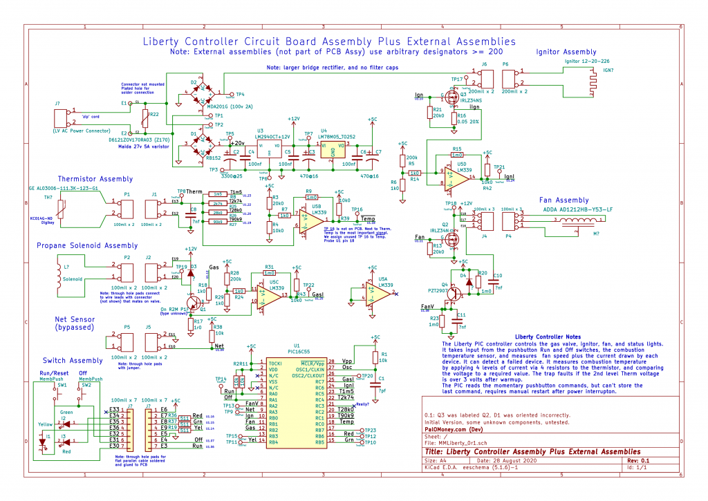
| − | The schematic is titled: Liberty Controller Circuit Board Assembly Plus External Assemblies | + | The schematic is titled: Liberty Controller Circuit Board Assembly Plus External Assemblies Rev 0.1 |
| − | + | [[File:LibertySchematic 0r1.png|1024px]] | |
| − | [[File: | + | Rev 0.1: Q3 was labeled Q2, D1 was oriented incorrectly. |
| − | + | Readers are encouraged to fill in missing information or correct any errors. Previous version: | |
| − | Readers are encouraged to fill in missing information or correct any errors. | + | [[File:MMLiberty Schem 0r0.png|256px]] |
== Circuit Description == | == Circuit Description == | ||
Latest revision as of 01:05, 29 August 2020
In September, 2014, a used MM Liberty was acquired to help out a Defender on a 1 acre formerly rural suburban property. It ran during the summer, but after running out of gas, it failed to start. Here is some documentation.
For more information, see the MM blog and the MM Forum.
Contents
Schematic Revision 1
The schematic is titled: Liberty Controller Circuit Board Assembly Plus External Assemblies Rev 0.1
 Rev 0.1: Q3 was labeled Q2, D1 was oriented incorrectly.
Readers are encouraged to fill in missing information or correct any errors. Previous version:

Circuit Description
The heart of the system is the MicroChip PIC16C55 28 pin PDIP micro-controller (uC) chip. This inexpensive, low end chip is one-time-programmable (OTP), and its firmware was programmed at the factory.
Along with the controller PCB, the Liberty uses 6 other assemblies: an AC power connector, a front panel switch and indicator assembly, a propane valve solenoid, an igniter, a fan, and a thermistor. These assemblies consist of the named component plus lead wires and female connectors that connect to mating connectors on the PCB, or are soldered in without connectors.
The PCB contains 2 rectifiers to rectify the incoming 20 volt pp AC low voltage power source, supplied by an external transformer and a long low voltage cord, the same as the Defender. High current rectifier D2 powers the igniter circuit directly, without any filter capacitors. The resulting full wave rectified AC waveform reduces the effective voltage somewhat for the 12 volt igniter. D1, the lower current bridge rectifier, powers the internal rails (power supplies). U3 implements a regulated +12v supply to power the fan, propane solenoid, and the +5 volt power supply. It could also be (but isn't) used as the Vpp programming voltage. U4 implements the +5v supply.
The front panel switches are momentary contact membrane switches reminiscent of 1980's era remote controls that always became intermittent. The switches ground one of two digital uC inputs. R1 and C1 form an RC network to support the PIC internal RC clock oscillator. The components result in a nominal 3(?) mHz clock frequency.
The uC's main outputs drive the fan, igniter, and the gas solenoid valve, in that order. Each external device is driven by a transistor, which in turn is driven by the associated uC output pins RB1, RB0, and RB2. These pins are actuated in a programmed sequence to power the associated devices.
The uC is powered from +5v, and will shut down if the power supply drops too low, which occurs when the trap loses power. Otherwise, the uC gets its information from three device monitor circuits plus the thermistor assembly, which measures the temperature in the combustion chamber after the catalytic converter. The idea is that the temperature should not be too low, or too high. If these conditions are not met, the uC shuts the propane valve, runs the fan for a few minutes, and blinks the LED to indicate a fault.
The thermistor is configured with 4 resistors (R8, R25, R26, and R27) to form a voltage divider that measures different thermistor resistances when voltage is applied to the 4 resisters in sequence. Capacitor C8 filters extraneous noise. The resultant voltage is applied to a comparator whose reference input includes some positive feedback for debouncing the signal. The wide range of resistance values permits measuring a wide range of temperatures, but with "above" and "below" resolutions only. The circuit is not capable of calculating a temperature rise or fall trend. This circuit is used to measure a operation in 4 bands of temperatures without using an A/D converter, an input common on other controller chips but not on this low-end device.
The three device monitor circuits measure the fan speed, gas valve current, and igniter current. If the fan speed is too slow, the FanV signal will go low after some time, and he uC knows the fan has failed or is not running. If the igniter current is not high enough, the igniter has failed (a frequent occurrence). If the fan solenoid current is too low, the solenoid has become open circuit (unlikely). Because the trap can detect these problems, service could theoretically become easier, provided the uC outputs an error code somehow. Perhaps it does.
Commentary
Compared to the Defender, these device monitor circuits and processing amount to a lot of expense and effort for very little reward. The Defender relies on just a continuous value temperature measurement plus the passage of time to tell whether to shut the trap down or not. And, as of this writing, the Defender is working, the Liberty is not.
The Liberty is worthy of a first attempt at the design of an potentially dangerous autonomous product that could leak propane and cause an explosion. It is easier to conclude that a design is safer if it has more monitors to check and alert when a component fails. Only with experience can confidence be had in more indirect algorithms that take longer to react.
The big problem is that the Liberty cannot recover from a power interruption because the uC cannot store the last command over a power loss. So, if the power goes off for longer than a moment, the trap will just stop, even though it may be quite hot (up to running temperature). This is a nasty design flaw to endure, especially given that membrane switches are so notoriously, laughably unreliable. "One push of a button" may sounds great for marketing, but is inconvenient during power interruptions from, say, thunderstorms, say, at dusk or at night. Good luck pressing those buttons then! How many bites did that take?
Planned Future Activities
The unit has not been further documented with oscilloscope traces and voltage measurements. Stay tuned.
I am considering how to substitute the NodeMCU WiFi controller now working in the Defender into this unit. See the MM Defender IOT Controller topic. The main issue is how to replace the membrane pushbuttons with a single toggle or rocker switch without completely ruining the unit so that it cannot be restored to its original operation.
Previous Analysis from 2015
Attaching an oscilloscope to the thermistor displays a repeating downward stair step, with each step lasting about 100 mS. One side of the thermistor at ground. The thermistor is bypassed with a capacitor to reduce noise.
The Liberty uses four fixed series resistors to measure the resistance of Liberty's 200 kOhm thermistor using voltage division. After applying 5 Volts to each resistor, the resulting voltage across the thermistor is measured. The cycle repeats every 400 mS.
The capacitor and thermistor are not used for timing like in the Defender, which uses variable pulse widths to continuously measure temperature. Instead, the Liberty circuit measures 3 important temperatures, plus a potential open circuit fault. This scheme is not self-calibrating.
[Although the Liberty Controller circuit has not been reverse engineered,] it seems evident that the thermistor voltage is measured by a comparator 4 times during a cycle. The On light is activated when the 2nd step voltage goes below ca 3.0 Volts, and the Fault light is activated when it rises above ca 3.0 Volts.
Using some logic we can speculate that the 1st step seems to be an over temperature protection scheme. It would go below 3 volts only if the unit got very hot. It never triggered during my test. The 2nd step is the desired temperature range -- below about 3 volts, the combustion is OK. Above, it is not. The 3rd step moves down quickly after ignition, to possibly indicate that the igniter is working and the unit is not just flooding the area with unburned propane. The 4th step seems to measure that the thermistor is not open-circuit. This was not tested.
Measured Stair Step Thermistor Voltages at TP8
Here are this Liberty's events and thermistor voltages for each of 4 consecutive steps vs elapsed time. The solenoid and gas control outputs would be a helpful addition.
| time | 1 | 2 | 3 | 4 | Notes |
| start | 4.8 | 4.2 | 3.2 | 0.4 | Press On/Reset. Warm Up Flashes. |
| 3:05 | 4.8 | 4.2 | 3.2 | 0.4 | Fan slows for ca 5 seconds |
| 4:05 | 4.8 | 4.1 | 3.1 | 0.4 | |
| 5:05 | 4.7 | 3.8 | 2.5 | 0.3 | |
| 6:05 | 4.6 | 3.2 | 1.8 | 0.1 | Warm Up LED Solid |
| 6:30 | Warm Up Solid. | ||||
| 7:05 | 4.5 | 2.4 | 1.1 | 0 | |
| 8:05 | 4.3 | 1.9 | 0.8 | 0 | |
| 8:36 | 4.1 | 1.6 | 0.6 | 0 | On LED Solid, Warm Up Off |
| 10:05 | 4.0 | 1.4 | 0.5 | 0 | |
| 11:00 | 3.9 | 1.4 | 0.5 | 0 | We turn gas off (On LED Solid) |
| 12:00 | 3.9 | 1.4 | 0.5 | 0 | |
| 13:00 | 4.0 | 1.5 | 0.6 | 0 | |
| 14:00 | 4.4 | 2.0 | 0.8 | 0 | |
| 15:00 | 4.6 | 2.8 | 1.4 | 0.05 | |
| 15:32 | 4.7 | 3.0 | 1.8 | 0.1 | Fault Solid |
| 16:00 | 4.7 | 3.4 | 2.0 | 0.2 | Fault Solid |
| 17:00 | 4.8 | 3.7 | 2.4 | 0.3 | Fault, Warm Up Solid, On Flash |
| 18:00 | 4.8 | 4.0 | 2.8 | 0.4 | |
| 19:00 | 4.8 | 4.1 | 3.0 | 0.4 | |
| 20:00 | 4.8 | 4.2 | 3.2 | 0.4 | |
| 20:37 | 4.8 | 4.2 | 3.2 | 0.4 | Fan Off |
More Later
The circuit can be instrumented and analyzed further. But that is for after mosquito season!