MM Defender IOT Controller Construction Details
Contents
- 1 Mosquito Magnet Defender IOT Controller Add-On Construction Details
- 1.1 Liability Disclaimer
- 1.2 Hazard Warning
- 1.3 Photos
- 1.4 Basic Steps
- 1.4.1 Assemble Tools and Supplies
- 1.4.2 Test and Fix the Original Controller
- 1.4.3 Acquire Materials
- 1.4.4 Set up Development PC & Software
- 1.4.5 Attach Header Pins to the HTU-21D
- 1.4.6 Flash and Test the Module(s)
- 1.4.7 Build the Wiring Harness
- 1.4.8 Modify the Controller PCB
- 1.4.9 Attach the Harness
- 1.4.10 Install Modified Controller into Trap
- 1.4.11 Test All Functions
- 1.4.12 Move Trap to Operating Location
- 1.4.13 Final Test
- 1.4.14 Monitor from PC and Phone
- 1.4.15 Periodically Check for Deterioration
- 1.5 System Requirements
- 1.6 System Design Description
Mosquito Magnet Defender IOT Controller Add-On Construction Details
Flash 6/16/2021 In testing the released software, the web interface failed to update the MQTT settings, and crashed. This occurred because the web server was not initialized, a statement was missing from the DefMain.lua module, which is compiled into the LFS package. After the modified units are deployed and working, an updated bug-fix release will be posted. In the meantime, the missing statement should be added to the existing DefMain.lua module module.start() function, DefMain.lua downloaded into the NodeMCU to override the pre-compiled version, and the web server should then work to update settings.
function module.start()
  setPost("")	-- dev_2021-06-13 - forgot this....

  t6.stop(t6)
  t6.alarm(t6, 10, tmr.ALARM_AUTO, timer100)
end
The web interface Save button saves settings in config.lua. You can do this yourself by uploading, editing, and downloading.
Time marches on. New software and a smaller controller board have inspired an update to this topic, coming soon. In the mean time, the download link is a zip file containing a new schematic for the new board, a rudimentary "mmmanual.txt" to give some clues as to the difference between the new and old, and the complete software for the new and older NodeMCU modules. This page will require significant reorganization to handle various hardware and software versions.
This is a rather large topic under construction. Current progress on the old software and hardware was about 93%. Because it is under construction, any printed copy will become obsolete quickly. This uncontrolled document's version is indicated by the last edited time and date on the page bottom. If using a printed copy, compare the last edited times. If not the same, use the web version or use the View History tab to see the changes between your printed and the current versions.
Recent posts on the Mosquito Magnet Forum have described a replacement controller that a skilled DIY (Do It Yourself) person can build and install. Poor manufacturing quality control plus harsh outdoor environments have caused some original controllers to become faulty with age. Additionally, it is quite difficult for DIYers even with troubleshooting instruments and technical expertise to troubleshoot a non-working trap using the original controller. What is missing is a mechanism to monitor and troubleshoot these devices so they can keep working into the future. The Mosquito Magnet MM Defender IOT Controller article describes an effective approach, but is lacking details on how to actually construct and implement the device. This article will supply more details. It is, however, necessary to discuss a few matters regarding this Mosquito Magnet Defender IOT Controller Add-On design, which partially explains why this topic was not written earlier.
Liability Disclaimer
By using any information on this website, you agree to the following:
These materials are presented "as is" and with no warranty or representation of any kind that this project or any other project described or referenced will function, that it or they will not be hazardous, or that the information here is complete or accurate. Rather, exactly the opposite is the case. The Add-On most likely will fail over time, and must be considered hazardous. The information here is incomplete and may contain inaccuracies.
This website and all its contributors and authors specifically disclaim any liability for incidental or consequential damages and assume no responsibility or liability for any loss as a result of the use or misuse of or reliance on any of the information or content of this website.
You agree to assume all the risks of building and using this or any project mentioned on this website.
Hazard Warning
First, the Mosquito Magnet traps use propane gas, which is flammable, and therefore dangerous. The original trap designers took great pains to make sure the trap would be safe. This is why the trap shuts down if everything is not "just so." While frustrated users being bitten might say that the trap is overly conservative and unnecessarily cautious, DIYers have not done the extensive analysis customary for a manufacturer of a potentially dangerous device.
Making and deploying a substitute controller, or any modification of a dangerous device, can be regarded as a risky or even reckless action. If something goes wrong, and there is an explosion, poisoning, or other calamity resulting in loss of life and limb, or property damage, do you want to have had a hand in the chain of events that possibly or even arguably might have caused it?
Second, the construction, modification, and installation requires tools and instruments plus experience with PCBs and micro component soldering. Those without the right tools or skills will find this project too difficult. Once modified, it is relatively easy but not trivial to revert to the original controller. If the modified system does not work, you may be stuck.
An error in wiring or controller modification, including errors caused by faulty directions here, can create a hazard. Additionally, wiring that is or becomes faulty can cause trap failure or incorrect and dangerous operation. It is relatively easy to break the wiring between the Add-On and the original controller, and it can and will deteriorate with outdoor use under normal use and weather conditions.
The prototype described here was developed to work with the one particular Mosquito Magnet Defender shown in the photographs. Another unit may not have the same design, and / or the components may not behave the same as in the prototype. Although directions for testing the modified system have been included, passing these tests is not sufficient to ensure correct operation under all conditions, or in the future.
This design is an Add-On to the original controller. Accordingly, other than the original PIC micro-controller, the original controller must be working because the IOT Controller Add-On just substitutes for the PIC. However, it is the failure of some of the parts of the original controller that might have caused the problem in the first place, and fixing those issues could restore the original controller to functionality. If the trap still does not work reliably, capable experts willing to assume the risk might choose to use the add-on controller to help identify those issues.
Third, the controller is an experimental device intended for use by experts to troubleshoot a non-working trap, and not as a permanent replacement for the original controller. As presently implemented, it lacks important features required for a permanent deployment. Some of these are: adequate mechanical support (mounting to the device), weatherproofing, and, critically, safety and functionality testing, validation, and certification.
Currently, the controller is supported only by the wires connecting it to the original controller PCB. Because it is not fully insulated, it must be positioned just so to avoid shorting to the trap metal parts. Although electrical insulation and some weatherproofing could be mostly jury-rigged by covering the controller with a plastic bag, this is not a permanent solution. This unprotected device does not and will not survive condensation and contamination from the elements.
Although wireless remote control makes physical contact with the device unnecessary, as an experimental device, it is desirable for it to be quickly and easily accessible for updating or substitution. This requires removing the catch basket and top cover. It is not easy to remove the top cover screws, so to avoid biting mosquitos, some may choose leave the screws out, which then results in yet another potential hazard.
Under no circumstances do we want anyone to endanger any life or property. Any servicing or modification of the trap is a dangerous undertaking. You should label any modified trap with a warning.
Remember, the add-on will not work reliably over the months or years due to lack of mechanical support and weatherproofing. Once your trap is working reliably, you should uninstall the controller add-on and revert to the original, unless you are engaged in active development, are willing to assume the risks, and willing to maintain and repair the modification as it corrodes or otherwise deteriorates.
These remarks, of course, apply to all DIY modifications, not just this one, which is intended only for troubleshooting and development. Finally, please be cautious, even if you improve upon the design.
Photos
Nothing to be too proud of here. Some burned insulation, scattered wires, no strain relief anywhere. Click on a picture to see it larger.
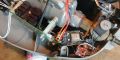
Loose placement of IOT Controller Add-On with optional Temp/Humidity sensor
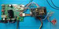
Controller with NodeMCU and Temp/Humidity attached
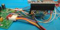
Front (or right hand side) view of IOT Controller Add-On showing 15 pin header wiring
Rear (or left hand side) view of IOT Controller Add-On showing power and thermistor connections
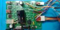
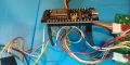
Placement of IOT Controller Add-On Wires on Original PCB.


There are 10 wires connecting the Add-On headers to the original controller, and 4 more connecting to the optional Temperature/Humidity sensor, which itself is flying off the Add-On. Nice work!
Observe the lack of strain relief and mechanical support, other than the 10 wires. This hack job is dis-recommended for long-term use. Note how easily the NodeMCU module or its uninsulated pins can come into contact with the metal trap parts. Be careful, or insulate, mount somehow, or all three.
Generally, the connecting wires are soldered to the most rugged attachment points available, through hole terminals if available, or soldered to a component and its pad if not. However, 2 wires are soldered only to pads, and these are fragile.
Refer to the schematic and description in The Mosquito Magnet MM Defender IOT Controller topic. For each wire or cut, locate its net and connection on the schematic. Some notes:
- C4 is effectively removed by cutting the foil to it (to the right of the middle white wire, a bit hard to see)
- On the prototype photo, the PIC controller has been completely removed (because it was fried). Otherwise, unsolder and lift pin 4 from its pad on +5v, and solder a very thin 1 strand jumper between the lifted pin and the adjacent pin #5. This sets the MCLR/ signal low, which effectively disconnects the PIC.
- Note the jumper between pin 14 and the top of R5 or pin 11. This connects VDD to R5 20k0.
- VDD is disconnected from +5v by cutting a foil on the bottom of the PCB (not shown).
- VDD is connected to +3.3v from the NodeMCU via the left orange wire.
- The right hand white and orange wires connect to the original ground and +5v rails near the electrolytic cap. These go to the rear or left hand side NodeMCU connector pins.
- The single pin white wire connects the ADC input to the bottom of R5.
- The WiFi antenna is on the front of the NodeMCU, and the USB connector is on the back. There is also a reset and a flash button, 2 status LEDs.
Basic Steps
- Thoroughly read the MM Defender Controller and MM Defender IOT Controller wiki pages.
- #Assemble Tools and Supplies
- #Test and Fix the Original Controller
- #Acquire Materials
- #Set up Development PC & Software
- #Attach Header Pins to the HTU-21D
- #Program and Test Module(s)
- #Build the Wiring Harness
- #Modify the Controller PCB
- #Attach the Harness
- #Initial Test Outside Trap
- #Install Modified Controller into Trap
- #Move Trap to Operating Location
- #Final Test
- #Monitor from PC and Phone
- #Periodically Check for Deterioration
Assemble Tools and Supplies
You will need the following tools, equipment, and supplies:
- 10x (opt. plus 50x) Stereo Microscope with illumination to clearly see what you are doing.
- Soldering iron with micro tip.
- Solder and solder flux.
- Fine solder wick, PCB cleaner, isopropyl alcohol, and brushes for cleaning.
- Contact cleaner for switches and connectors (e.g., DeOxit).
- Brush-on conformal coating (e.g., MG Electronics 4223 (urethane) or 422B (silicone))
- Micro tweezers for surface mount device (SMD) placement and manipulation.
- A fine gauge (diabetes) medical syringe is helpful for prying and scraping.
- Volt-Ohm Meter (VOM) with suitable test leads.
- Clip leads for testing, plus a 1k or so resister for forcing the driver transistors on.
- Oscilloscope, single or dual channel, calibrated, with probes. 10 MHz or higher. 1 MHz might work with allowances, not tested.
- Diagonal cutters and wire stripper for fine (e.g., 24-32) gauge stranded wire.
Test and Fix the Original Controller
If the original controller is not working, or even if it is, it is a good idea to remove, clean, and inspect it thoroughly.
- The 3 standoffs holding the board will have become brittle with age. Be careful when removing the board from the standoffs, and press the release tab on the component side before very gently pulling the board out. If you break a standoff, you can replace it (Richco SCBS-16-01), or tap the body for an 8-32 stud. The same goes for the nylon thermistor bolt, it should be replaced every service time (8-32 x 1/2").
The original controller PCB is lightly (inadequately) sealed with a sealer for weatherproofing. Accordingly, you have to scrape off the sealant to probe a pad.
- Measure the resistances of the fan (?? Ohms, although it either works or it doesn't), igniter (0.9 - 1.4 Ohms), solenoid (?? Ohms), and thermistor (200 kOhms). If these are either too low or too high, they must be replaced.
- Measure the resistance across C4: Disconnect the thermistor. Attach the VOM negative lead to the negative (ground) terminal of power supply filter cap C2 (large 3300 uF @ 25v) and the positive lead to J1 terminal 1. The resistance should be in the meg-Ohm range (this is from the PIC). If it is low (e.g., 20 kOhms), your controller is suffering from the "C4 PCB contamination" issue discussed on the controller wiki page. If low,
- Carefully unsolder C4 (ca 120 nF ceramic, was previously marked 150 nF). Remove the coating from the PCB in the vicinity of the pads. Thoroughly clean the PCB between the pads. Measure the resistance again until it is in the meg-Ohm range. Measure C4, then carefully strip and clean as necessary until infinite resistance is obtained. Build up a solder blob on each mounting pad. Solder C4 to the blob to allow space underneath for cleaning. Thoroughly clean and measure. When in the meg-Ohm range, seal the area with a conformal coating. Use two coats. Very critical, and a major reason the original units failed.
- With the 'scope, measure the power supply voltages and ripple voltages. See that the ripples are symmetrical, and not too large for the D1 C2 +20v supply. The large bridge rectifier D2 has no filter cap, and will show all ripples. Attach the igniter and ground the J5 pin 2 lead to power the igniter, and see that the voltage does not just collapse. The RMS value should be appropriate for the 12 volts igniter. The igniter should light up, and be hot enough to ignite a propane torch. This also tests the power supply and long low voltage cord. If there is a problem with insufficient power, check the AC side of the supply to isolate the problem to the supply/cord or D2 rectifier bridge.
- Measure the +12 and +5v rails, they should be without ripple.
- Attach the fan, thermistor, switch, and gas valve solenoid. Power the unit again, and observe the low (ground) side of the Igniter, Fan, and Valve go from +12 to 0 volts as the driver transistors switch on. Check the switch LED to see that it flashes on power up.
If any of these tests fail, there is a problem with either the driver transistors, the controller, or the switch that must be fixed before the IOT Controller Add-On can be used.
- Check the switch terminal to see that it goes between +5v (off) and ground (on) when actuated. Make sure that wiggling the wires to the switch has no effect in either position.
- Use the 1 kOhm or so resister in series with a test lead connected to +5v rail (supply voltage) to test the driver transistors. You may have to scrape a pad (e.g., on the C7 + pad on the underside) and possibly solder a small piece of solid wire to access the +5v rail. Attach a clip lead to +5v and one end of the 1 kOhm resistor. Touch the other end to the base or gate of the driver transistor to force it on. Measure the voltage across the fan, igniter, and valve terminals to see that it goes on when the 1 kOhm signal is applied to the gate or base of the driver transistors. If the voltage does not read 12v when driven, the transistor is defective, or possibly the igniter, fan, or valve solenoid is shorted.
- With the scope, measure the voltage on the low side of the connection to the fan, igniter, and solenoid. When they are off, the voltage should be at the +12v rail. When on, it should be at only a few millivolts of ground. If the voltage is higher (e.g., over 1 volt), then the driver transistor is not being saturated, and will dissipate too much power and get hot, leading to failure. Record (write down) the saturation voltage for later comparison to operation with the Add-On. Test the temperature of the drivers. If too hot to touch, there is a problem that must be fixed.
If these tests are passed, perhaps you have fixed the problem, and can use your trap as is, provided the PIC controller works. Try it.
- If working, catch some mosquitos and stop here.
- If not, you can continue with the IOT Controller Add-On.
Acquire Materials
Per unit, the NodeMCU is about $6, the optional HTU21D is ~$4, and the header, the wires, and the heat shrink tubing are hopefully "lying around" somewhere. Of course, you will want to buy multiples for backup and experimentation.
- 1 or more ESP8266 ESP-12E NodeMCU modules, from any number of vendors, e.g., "MakerFocus ESP8266 NodeMCU LUA CP2102 ESP-12E Internet WiFi Development Board Serial Wireless Module." Cost about $12 for 2 (get 4).
- (optional) 1 or more HTU21D Temperature/Humidity module, e.g., "HiLetgo HTU21D Temperature Humidity Sensor Breakout Module I2C IIC 1.5V-3.6V." Cost about $7 for 2.
- 1 40 pin female header strip, e.g., "10 Pcs 40 Pin 2.54mm Pitch Straight Single Row PCB Female Pin Headers." You should already have these, but the cost of about $6 for 10 pieces, yields a lifetime supply.
- Several colors of thin (28-32) gauge, stranded, flexible, 200°C, very high quality hookup wire with high temperature PTFE or Teflon insulation, e.g., "Alpha 2840/7." This example uses white, red, blue, orange, yellow, violet, and brown. Try to "borrow" the short lengths of wire from a "friend," otherwise it could get expensive (e.g., $70 for 100' reel, each color) to buy wire for this project.
- Do not use stiff or cheap wire. It will break with handling, melt, or tear the PCB board. The colored wire in flat cable may be tempting, but is especially unsuitable. If you do use stiff wire, it must be well strain-relieved on both the PCB and header ends.
- Heat shrink tubing is useful for insulating the terminals on the rear or left hand side of the module.
Set up Development PC & Software
The most convenient tools are java apps. Also, there is a python module that downloads the Lua environment (OS with optional function modules) onto a new NodeMCU.
- Connect the ESP-12E Module to the PC via USB. If necessary, install the CP2102 Drivers to create a new COM port.
- Install Java, if not installed.
- Download and install ESPlorer, a java Integrated Development Environment (IDE) for ESP8266 developers.
- Download and install mqtt-spy, a java MQTT client.
- Download NodeMCU Flasher for Windows or the python esptool.py.exe. There are many options available, pick the one you like.
- Download a suitable MQTT client to your phone (e.g., MQTT Snooper).
Attach Header Pins to the HTU-21D
- Solder a 4 pin male header (included) to the board opposite the component side.
- Attach 4 leads of a 5 conductor female-female jumper cable to the corresponding pins of both units. The colors don't matter.
| position | color | net | NodeMCU |
|---|---|---|---|
| 1 | blue | cl | pin 26 D4(GPIO2) |
| 2 | brown | da | pin 27 D3(GPIO0) |
| 3 | white | - | pin 17 gnd |
| 4 | orange | + | pin 16 3.3v |
Flash and Test the Module(s)
Install the NodeMCU Lua environment
The v3.1 software was finely tuned to work with the July, 2018 lua firmware. The current software requires a few minor modifications to work the September, 2019 firmware without error. More importantly, the running software has about 3500 fewer bytes of RAM available, which makes it much less robust, and prone to rebooting when accessing the web page. Accordingly, to use the v3.1 (and planned v3.2) software, skip the next step:
- [Not yet:] Go to NodeMCU Cloud build service and select the following 11 sub-modules: adc, enduser_setup, file, gpio, i2c, mqtt, net, node, tmr, uart, and wifi. You may choose to build a development branch or the master branch. Submit the build request, wait for the "build complete" email, and click the link to download the built floating point firmware.
Instead of using the current firmware build service:
- Download the July, 2018 Lua firmware from here.
- Flash the module to install the NodeMCU Lua environment. For example, to install the version 11 development branch floating point version.
esptool.py.exe -p COM3 write_flash -fs 32m -ff 80m --flash_mode dio 0x00000 C:\mmdefender\Install\nodemcu-dev-11-modules-2018-07-21-20-46-15-float.bin
esptool.py v2.3.1
Connecting....
Detecting chip type... ESP8266
Chip is ESP8266EX
Features: WiFi
Uploading stub...
Running stub...
Stub running...
Configuring flash size...
Flash params set to 0x024f
Compressed 458752 bytes to 297898...
Wrote 458752 bytes (297898 compressed) at 0x00000000 in 26.4 seconds (effective 139.0 kbit/s)...
Hash of data verified.
Leaving...
Hard resetting via RTS pin...
- Open ESPlorer and select COM3 or whatever port the module is using. Press the module reset button. ESPlorer responds:
Formatting file system. Please wait...
NodeMCU custom build by frightanic.com
 branch: dev
 commit: fd745e0981ca2c4d425c966334cef67180f0cb63
 SSL: false
 modules: adc,enduser_setup,file,gpio,i2c,mqtt,net,node,tmr,uart,wifi
build created on 2018-07-21 20:45
powered by Lua 5.1.4 on SDK 2.2.1(6ab97e9)
lua: cannot open init.lua
Not opening init.lua is a good thing because nothing is programmed into the unit yet. Pressing the FS Info button shows:
Total : 3447234 bytes
Used  : 0 bytes
Remain: 3447234 bytes
A 3.5 mb empty file system onto which we will load the firmware.
Install the MM IOT Controller Software
- Download and unzip the latest software into a folder.
The following steps use ESPlorer:
- For each file in the release, upload the file into the NodeMCU module.
- Press the right hand "Reload" button to display the files in the module.
- For each .lua file uploaded, except init.lua and config.lua, right click the entry and select "Compile xxx to lc." Compiled code takes less program memory, which is very scarce.
- Press and release the RTS button to reset the module, and notice the additional output after the "powered by Lua" sign-on, e.g.,
39024
'tmr.stop(6)' within 5 seconds to stop running
- You have 5 seconds to type "tmr.stop(6)" on the bottom command bar and hit send, otherwise the main controller program starts. You would do this to upload a modified source file and compile it for your next revision of the software.
Test the MM IOT Controller Software
Press and release RTS to restart the unit and wait for it to start.
39024
'tmr.stop(6)' within 5 seconds to stop running
> 38176
starting system
30416
30472
25176
23712
15640
15984
Wifi...
12752
8896
These declining numbers are the number of free CPU memory. If the Lua OS runs out of memory, it panics and restarts. Free memory is so important, it is reported every second as "M=" below. This example uses the optional htu21d module, otherwise maximum external temperature (T=) and humidity (H=) readings are reported.
Temp=-43.7C (-43.7) at 0:0 F=0 I=0 G=0 S=0 E=0 T=25C H=46.6% M=9752 (9/9:18804706) R=70~140 B=-19.0 V=3.1
state = 0 was 7 at 1 (0)
Temp=-43.7C (0) at 0:0 F=0 I=0 G=0 S=0 E=0 T=25C H=46.5% M=9584 (9/9:18804706) R=70~140 B=-19.0 V=3.1
Temp=-43.7C (0) at 0:1 F=0 I=0 G=0 S=0 E=0 T=25C H=46.5% M=8176 (9/9:18804706) R=70~140 B=-19.0 V=3.1
Temp=-43.7C (0) at 0:2 F=0 I=0 G=0 S=0 E=0 T=25C H=46.3% M=8200 (9/9:18804706) R=70~140 B=-19.0 V=3.1
Temp=-43.7C (0) at 0:3 F=0 I=0 G=0 S=0 E=0 T=25C H=46.2% M=8208 (9/9:18804706) R=70~140 B=-19.0 V=3.1
The first time, skip to #Configure the Wifi. After you set up the wifi connection, you will get
Connected to wifi as:(omitted)
9208
Starting Web Server...
Connecting to: test.mosquitto.org:1883 User: Pwd: ID:11823997
Subscribing to: /test/MMD/esp11823997Q
Ok
Temp=-43.7C (0) at 0:4 F=0 I=0 G=0 S=0 E=0 T=25C H=46.2% M=6232 (9/9:18804706) R=70~140 B=0.0 V=3.1
At some point, the OS starts garbage collection, and the free memory rises to about 11 kbytes:
Temp=-43.7C (0) at 0:5 F=0 I=0 G=0 S=0 E=0 T=25C H=46.2% M=7320 (9/9:18804706) R=70~140 B=0.0 V=3.1
Temp=-43.7C (0) at 0:6 F=0 I=0 G=0 S=0 E=0 T=25C H=46.2% M=7304 (9/9:18804706) R=70~140 B=0.0 V=3.1
Temp=-43.7C (0) at 0:12 F=0 I=0 G=0 S=0 E=0 T=25C H=46.4% M=7312 (9/9:18804706) R=70~140 B=0.0 V=3.1
Temp=-43.7C (0) at 0:13 F=0 I=0 G=0 S=0 E=0 T=25C H=46.4% M=11304 (9/9:18804706) R=70~140 B=0.0 V=3.1
Temp=-43.7C (0) at 0:14 F=0 I=0 G=0 S=0 E=0 T=25C H=46.3% M=11344 (17/16:18804706) R=70~140 B=0.0 V=3.1
Temp=-43.7C (0) at 0:17 F=0 I=0 G=0 S=0 E=0 T=25C H=46.2% M=11352 (17/17:18804706) R=70~140 B=0.0 V=3.1
and so on. Adding code or variables will reduce this value. The 11 kb value was obtained after several passes at eliminating or optimizing the code and variables until the unit was reliable (didn't crash) when stressed with commands and web page requests.
Optionally, carefully connect a clip lead between a NodeMCU ground pin (e.g., pin 24 or 14) and pin 21 (switch) input, and observe the S=1 value. Do not blow up the NodeMCU pin with a static discharge! Observe the software go through a start cycle, and eventually fail with error E=7 in state 7 (sFAIL). You can set the switch to Off by connecting it to a 3.3v pin, and see how the system eventually goes back to state 0 (sOFF).
Configure the WiFi
When not connected to a wireless network, the controller creates its own access point named "SetupGadget_######" where '#' is some number.
- Connect to that access point, and very quickly open in a browser any web address (e.g., google.com or http://t.c) to display a web page with a list of access points with good reception.
- Note: the controller access point and web page is on only when the controller does not have a wireless connection.

- Select or enter an SSID and enter the password. The controller will try to connect and display the IP address it has received via DHCP (e.g., 192.168.1.32).
Configure the MQTT Client

- Open the controller's web page with the above address followed by :8080 (e.g., 192.168.1.32:8080).
- If you can now access this web page, the controller does have a wireless connection, so its access point is not on.
- Here you can control the unit's MQTT settings, and change the WiFi settings as well. You can change and save the access point, or just restore the defaults to erase it.
- If it doesn't work, restart or power cycle the controller to start over.
Test the MQTT Reporting
Although the ESPlorer console displays the controller status, when deployed, the controller gets its power from the original controller +5v rail, not the USB.
- Do not connect the USB to a powered on trap. The results are unpredictable, and not good. You may damage your PC or the original controller, or who knows what? You may have to remove the controller from the trap to use the USB connection.
- Open mqtt-spy and create a connection to whatever MQTT server was specified on the controller web page. Subscribe to the specific topic configured. You should see your data stream match the info on the console.
- You can configure mqtt-spy to save a log file, with size rotation, etc. This is very helpful to troubleshoot problems over several days worth of operation. You will need an editor (e.g., notepad++) that can open a large text file, and update the file as new data is appended.
- Open your phone's MQTT client (e.g., MQTT Snooper), connect, subscribe, and observe the data stream.
Test the MQTT Commands
- For each command listed below in the #MQTT Commands section below, send a message to the command topic (by default the status topic with a suffix) and observe the specified response.
When you have all of this working, you can continue to building the wiring harness, modifying the controller, and installing the Add-On.
Build the Wiring Harness
- Cut a 40 or so pin 100 mil female header down to 15 pins. Sand the cut edge so you don't get injured.
- Cut appropriate lengths of colored wire. The initial prototype shown here might have the wires a tad short. The Add-On should not suffer from tight wires. The signals are not critical, a little extra length will not hurt.
- Solder one end of each wire to the appropriate pin on the header. Your colors may differ from these:
| position | color | net | destination |
|---|---|---|---|
| 16 | orange (& or) | 3.3v | HTU21D '+', (TTL 3.3v) |
| 17 | white (& wh) | ground | HTU21D '-', (TTL ground) |
| 18 | (green) | TxD0 | (TTL serial transmit) |
| 19 | (red) | RxD0 | (TTL serial receive) |
| 20 | yellow | Gas | R10 and PIC #8 |
| 21 | violet | switch | J1 pin 1 |
| 22 | blue | FAN | via & PIC pin 7 (delicate!) |
| 23 | green | thermlo | R5 |
| 24 | white | ground | J1 pin 2 |
| 25 | orange | 3.3v, VDD | J1 pin 3 |
| 26 | yellow | sdl | HTU21D SDL |
| 27 | violet | sda | HTU21D SDA |
| 28 | n/c | n/c | n/c |
| 29 | red | Ign | PIC pin 6 (delicate!) |
| 30 | brown | LED | R2 and PIC #1 |
Unlike the prototype, each wire should be insulated and strain relieved. The 4 optional TTL level serial connections are shown in parenthises.
You can use another 15 pin connector, but it is easier to use a 2 pin and 1 pin header (although you must never flip the 2 pin header).
| position | color | net | destination |
|---|---|---|---|
| 1 | white | adc & tock1 | R5 low side to thermistor |
| 2-13 | n/c | n/c | n/c |
| 14 | white | ground | C6 - |
| 15 | orange | Vin +5v | C6 + |
Modify the Controller PCB
To restore the original controller, these steps must be undone. Do them carefully with an eye to eventual restoration.
- Make sure the propane tank is outside and off.
- Cut the foil to C4 near R5 and R6
- Unsolder and use a thin gauge needle or syringe to carefully pry and slightly lift PIC pin 4 from its pad on +5v, then solder a very thin (e.g., 40 gauge) 1 strand jumper between the lifted pin and the adjacent pin #5 (ground). This sets the MCLR/ signal low, which effectively disconnects the PIC (according to the spec, not tested). The alternative is to remove the PIC completely (not recommended).
- Solder a jumper wire between pin 14 and the top of R5 or pin 11. This connects VDD to R5 20k0.
- Locate and cut the foil on the bottom of the PCB connecting VDD to +5v to create the new net +5C, which will be fed 3.3 volts from the NodeMCU.
Attach the Harness
Carefully solder the harness wires to the strongest terminals first, then finish with the most delicate.
- The right hand white and orange wires connect to the original ground and +5v rails near the electrolytic cap. It might be better if they were longer and attached to the PCB bottom to the through hole electrolytic cap.
- The single pin white wire connects the ADC input to the bottom of R5.
- Strain relieve the two most delicate connections to prevent tearing up the foils with handling.
Install Modified Controller into Trap
- Make sure the propane tank is outside and off.
- Disconnect the USB and connect the NodeMCU module to the headers. Connect the HTU21D.
- Position the NodeMCU as shown. The WiFi antenna should not be blocked by metal. Avoid the trap metal parts, which would possibly overheat and certainly short out the module. You may want to construct some cradle that could support the module in a known safe position. Do not conduct heat from the trap to the module. This mounting should withstand temperatures of over 100°C. The wires should be rated for 200°C.
- The optional temperature / humidity sensor HTU-21D can be positioned more freely. However, the module is not weatherproof. Avoid placement where rain can flood the humidity sensor.
Test All Functions
Test all functions to make sure that they work properly. As noted in the Hazard Warning section above, passing these tests is not sufficient to ensure correct operation under all conditions, or in the future. If any test fails, stop and fix the problem. Do not continue.
- Make sure the propane tank is outside and off. Turn the On-Off Switch Off.
- Connect the igniter, fan, valve, solenoid, and switch. Plug the trap into the power. The fan will briefly spin.
- With a scope, measure the +12v, +5v, and +5C rails. +5C should read +3.3v. There should be no visible ripple on the +5V and +5C rails.
- Observe the unit using mqtt-spy or your phone or the web page. Read the thermistor temperature. It must be within a few degrees of the external temperature.
- Turn the On-Off Switch On. Observe the fan turn on and the LED blinking.
- Observe the unit progress through the start-up cycle, and check that the fan, igniter, and valve solenoid all work in sequence.
- With the scope, measure the voltage on the low side of the connection to the fan, igniter, and solenoid as they turn on. When they are off, the voltage should be equal to the +12v rail. When on, the voltage should be at only a few millivolts above ground. See the earlier controller test. Compare the voltages to those recorded earlier. If the voltages are significantly higher, the add-on is not driving the transistors sufficiently, and the drivers will overheat. Hot devices could fail open or shorted. Do not let the driver transistors operate hot, especially the solenoid driver. A shorted solenoid driver will keep the propane flowing regardless of combustion, a catastrophic failure.
- Verify the LED blinking codes. The unit will fail to start without propane connected. Use the MQTT client to observe the unit going into the error state (7) after several minutes.
Only if all tests have passed, continue to the outside installation and test.
Move Trap to Operating Location
- Move the trap outside, connect the propane, and observe the data stream on your phone using an MQTT client.
- Observe trap startup. With the top cover off, you may have to block much of the fan using a piece of paper to reduce the air flow to get a combustible air-fuel mix.
- Verify the LED blinking codes. When in steady state, the LED must be on solid.
- The trap should reach 100°C and higher.
Final Test
- Remove the paper, and place the cover over the trap, taking care to not crush any wires, or knock the Add-Ons. Install an empty catch basket.
- If it seems Ok, go inside and let it run, observing it using the MQTT client and web page.
- If all is well, prepare a fresh attractant cartridge for your trap. Put it in.
Monitor from PC and Phone
- Refine your MQTT client configuration to save log files, record only one unit, etc.
- If the unit fails (internal temperature drops to under, say, 90°C), open the log file and find the time this started, then develop a theory as to why this happened, and take a corrective action, and try again. Repeat as necessary.
Post your findings on the forum. Welcome to the club!
Periodically Check for Deterioration
The prototype unit shown here failed because of contamination and corrosion. The symptom was an occasional loss of WiFi connectivity, and periodic rebooting. Upon examination, the unit was contaminated with gooey mosquito and other organic material, and the connecting pins were corroded and rusted onto the connector, requiring some force to unplug. Replacing the unit with the alternate module and cleaning the connectors resolved the problem. After cleaning and rust removal, the replaced NodeMCU worked except for the CP2102 USB-serial function, which failed even though it was never connected or in use when in the trap. The NodeMCU omits the customary USB protection diodes, which are recommended by the chip manufacturer.
- Every month or so, examine the Add-On for contamination and corrosion. Unplug the connectors, clean and dry the module(s), and spray contact cleaner or other protector on the pins and connectors. You can try covering with a high temperature plastic covering, but do not block the WiFi signal, and do not create an oven to bake the module. The temperature and humidity sensor must be exposed to work.
System Requirements
The Defender IOT Controller Add-On ("Add-On") is intended to replace the Mosquito Magnet Defender PIC micro-controller to provide additional functionality for monitoring and troubleshooting lacking in the original controller.
1 Compatibility
1.1 The system shall operate in the same manner as the original controller such that a user can check and operate the trap without accessing it via the WiFi.
1.1.1 The system shall obey the On-Off switch. Any fault shall be cleared by the user cycling this switch, and the trap shall restart as is done by the original controller.
1.1.2 The system shall drive the On-Off switch LED with the same solid or blinking codes as the original controller.
1.1.3 The system shall detect and respond to fault conditions. It shall disconnect the propane source upon a detected malfunction similarly to the original controller.
1.1.4 The system shall function identically in the absence or failure of a WiFi connection or signal.
1.2 The system shall require a minimum of modification to the original controller assembly to facilitate reversion to the original controller.
1.3 The trap shall be prominantly labeled to indicate that a delicate experimental controller Add-On has been temporarily installed. The label should include a warning to not move or disturb the trap.
2 Remote Operation
2.1 The system shall support two-way remote control and status communication with a PC and Smart Phone.
2.1.1 The system shall measure and report important operating characteristics such as relevant temperatures, sensor inputs, control outputs, state, faults, operating times, system resources, operating parameters, and other information of interest.
2.1.1.1 These reports shall be suitable for remote logging and automated analysis from one or more simultaneous locations.
2.1.2 The system shall respond to remote commands to restart the system, restart the combustion cycle, stop the trap operation by putting the system into a fault state, and optionally, change certain operating parameters, exercise the control outputs, and change the state for troubleshooting.
2.1.2.1 The system shall not implement commands that could put the trap into a potentially dangerous state.
2.1.2.2 The system shall support timed operation initiated by a remove computer by accepting a special fault command to turn the trap off, and a restart command to resume operation.
2.2 The system shall periodically attempt to reconnect to a failed network or connection.
2.2.1 WiFi/MQTT: specifically a failed Wifi VLAN or a failed MQTT or other reporting and control server.
2.3 The system shall support a means of security to prevent unauthorized access to the control functions.
3 Remote Configuration
3.1 The system shall have a means for remotely configuring the communications method and connection end points independent of the primary communication channel.
4 Software Updates
4.1 The system shall support software updates via serial or USB connection, and optionally, by automatic live remote over the air (OTA) updates from a specified server.
4.2 The system shall support a future additional level of functionality that might add additional hardware sensors and control functions.
5 Specific WiFi / MQTT Requirements
5.1 The system shall support an existing WiFi VLAN infrastructure using WPA2 security.
5.2 The system shall implement an MQTT client for reporting and control.
5.3 The system shall provide its own access point and web page for initial WiFi setup to select an infrastructure VLAN supporting WPA2 security.
5.4 The system shall provide a configuration web page to set essential communication parameters, and modify or reset the WiFi connection settings.
5.4.1 The system shall include setup instructions on its configuration web page.
Notes
- The system is not designed to support simultaneous USB and trap power. Connecting USB power while the trap is powered may damage the trap, the Add-On, and the USB hub (or PC).
- It may be possible to monitor and configure the system with a PC running ESPlorer or a terminal application via a USB serial to TTL adapter connected to an optional TTL level serial connection to the RxD0, TxD0, ground, and 3.3v pins while the trap is powered. This has not been tested when installed in the trap.
- Requirements for mounting, insulation, strain relief, weatherproofing, testing, and certification have been omitted. Accordingly, these units will be become unreliable over a period of time. Conformal coating the connections, spraying the connectors with anti-corrosion and anti-oxidation chemicals, and covering the unit with a plastic or other material to reduce the effects of condensation and contamination may improve its longevity, but you should consider this Add-On temporary and anticipate periodic maintenance over the course of its use.
System Design Description
The MM Defender Controller and MM Defender IOT Controller wiki pages are included here by reference, and the relevant parts are part of this description.
The Defender IOT Controller Add-On ("Add-On") is implemented using a very inexpensive Internet of Things (IOT) NodeMCU controller module. This 30 pin device includes an Espressif Systems ESP8266 ESP-12E WiFi Module mounted on a PCB containing a 5v to 3.3v power supply and a CP2102 USB to serial adapter chip. The Add-On gets power from the original controller +5v, or from a USB cable attached only when the trap is unpowered.
From Wikipedia: "NodeMCU is an open source IoT platform. It includes firmware which runs on the ESP8266 Wi-Fi SoC from Espressif Systems, and hardware which is based on the ESP-12 module. The term "NodeMCU" by default refers to the firmware rather than the development kits. The firmware uses the Lua scripting language."
The NodeMCU costs about $6 and the system is open source (so no malware).
Why MQTT
The MQTT system was designed for very lightweight IOT devices to communicate meaningfully with other devices and controllers. Because it uses a highly available 24/7 server (know as a 'broker') as it's endpoint, the device is isolated from any issues from loss of connectivity to a single PC. Additionally, any number of PCs and processes can easily get data from the broker, and run automated analysis and control, for example to turn the trap on and off depending on weather conditions and time of day. There are several free public MQTT brokers available, e.g., broker.hivemq.com that offer excellent free service.
Security
The free servers however are free for anyone to connect and observe your data, and potentially control your device. If this is unacceptable, you can run your own private MQTT server on a computer on your network or on the cloud, or use a paid subscription service that requires an authenticated log in.
The system also uses security through obscurity, a handy but discredited practice. The command channel uses a suffix that should be user configurable, but is currently a hard-coded literal. The commands are published here. You can easily change the suffix and commands in the source code, although any secrets are revealed upon sending a command, which can be seen by all who can access the MQTT messages on a public broker.
There is no combination of commands that could put the trap in a dangerous state. For example, there is no way to turn the Gas on without ignition or existing combustion. The main risk is denial of service from an unauthorized person sending a command to turn off the trap, or restart it periodically so it never reaches operating temperature, and consumes the limited-life igniter.
Why Lua
The NodeMCU Lua OS supports event driven functions, and programming Lua is like writing Windows functions. There is no main loop. Instead, the software registers functions with event sources and are called when the event occurs. The most common source is a timer. A timer is used to send commands to and read, for example, the i2c bus. The Lua code does not use delay loops to wait, but sets a timer instead. The code must not tie up the processor looping because it would interfere with other real time functions, such as the WiFi connections or serial ports.
Lua code can be interpreted as is or the NodeMCU can compile it. The compiled code runs faster and takes up less precious RAM space. The system swaps compiled or interpreted code into RAM as needed.
This project uses 11 Lua sub-modules: adc, enduser_setup, file, gpio, i2c, mqtt, net, node, tmr, uart, and wifi. The Lua system or environment is custom built by specifying these libraries, then the floating point version is downloaded into a NodeMCU module. The 128 kByte RAM is mostly consumed by the system, which leaves about 39024 bytes of free memory for code and data.
Tight Coding Style to Save RAM
The big disadvantage of the standard, unenhanced Lua environment is the very small remaining code and variable memory after several libraries are built into the environment. There is a relatively new option to support running code from the 4 mByte flash memory, which will allow vastly larger code and variable sizes, but that has not been used in this version. Code and variables share the RAM. This makes it hard to add new features. With all the modules loaded and initialized, and after garbage collection, only about 11 kB is left for program heap RAM. This 11 kB has been sufficient for normal operation. Adding code or variables reduces this value. The 11 kB value was obtained after several passes at eliminating or optimizing the code and variables until the unit was reliable (didn't panic) when stressed with commands and web page requests. Compiling most of the modules saved bytes. Replacing constant identifiers, which are Lua variables, with literals also saved bytes. Comments were minimized throughout so modules could be debugged, although they are later compiled when not debugging. Code was moved into the html file, which could be any size, to implement the dynamic web page. Different coding tricks were tried to minimize memory usage, until the system worked reliably.
Report Versions
The system reports a software (3) and report (1) version on each message. This is to aid parsing by analysis programs. The current version contains some values, such as the raw adc values and calculated thermistor resistance, that may be less important than more critical values. However, every value was added to troubleshoot some issue during development.
The prototype Defender dates from 2004. Many components have been replaced. To this day, it exhibits very odd, so far unexplained, behavior. See the MM blog and the MM Forum and the original MM Defender Controller, which is a combination wiki and blog showing the struggles over the last few years. Other users will have other requirements, and so should feel free to change the report to meet their needs.
Features, Defects, and Issues
All software has defects, otherwise known as bugs. This software is no exception. This code is especially difficult to review in part because comments have been very limited to save memory. Some functions are unreliable and insufficient resources have been directed to making them more robust. Not all specified or desired features have been implemented.
- The software rarely loses its MQTT connection and does not successfully resume publishing even though the network and server are or have become available.
- The Cool off command message does not assign the error code, so it cannot be used to shut down the trap via an external timer.
- The v3.1 sLOW state does not activate the gas. It was used to heat up the igniter so that when the gas came on, it would ignite immediately, and not explosively. However, research of the original controller's indicates that both are turned on at the same time as the fan speed is reduced to make a rich fuel/air mixture.
- There is no sensor to measure the tank capacity or gas pressure.
- No mounting, strain relief, or weatherproofing.
- The On-Off switch LED is too dim.
- After an AC power loss, the module sometimes loses its WiFi connection, requiring connecting to the access point and entering WLAN information again.
- (Not an issue with the software) Some smart phones detect a lack of internet connectivity, and abandon a WiFi access point after a few seconds if another known network is available. Accordingly, it is important to very quickly open a direct url web page (e.g., "http://t.c") in a browser after connection to the setup access point.
Software Module Listing
The MM IOT Controller Add-On source consists of 8 Lua source files, plus a page and some graphics for the communications settings web page:
DefMain.lc      : 4992 bytes     -- compiled version
DefMain.lua     : 8008 bytes     Controller logic
StationAp.lc    : 592 bytes      -- compiled version
StationAp.lua   : 630 bytes      Configures an access point to set up WiFi
Wifi_0.jpg      : 15456 bytes    Screen shot of the StationAp web page
arctile.jpg     : 6106 bytes     Background for the web page
conf.htm        : 3682 bytes     Configuration web page
config.lua      : 258 bytes      Current configuration settings
favicon.ico     : 9062 bytes     *Icon that displays in a browser tab - this one cannot be used.
htu21d.lc       : 1992 bytes     -- compiled version
htu21d.lua      : 1701 bytes     Controls the optional temperature/humidity sensor
init.lua        : 741 bytes      "Main" module loads other modules
mosqtile256T.gif : 5009 bytes    *A graphic that is tiled as a web page background
mqtt_svr.lc     : 2600 bytes     -- compiled version
mqtt_svr.lua    : 2787 bytes     Interfaces to the MQTT client
www.lc          : 3912 bytes     -- compiled version
www.lua         : 4809 bytes     Displays and handles the configuration web page
----------------------------
Total file(s)   : 17
Total size      : 72337 bytes
Note: files marked with an asterisk (*) are copyrighted, and must be replaced with a substitute prior to public release. Version 3.2 is the current development version, which should more closely implement the system requirements. Also, liability issues and where to distribute are being considered. Users wishing to obtain the software should participate in the forum discussion to facilitate resolution of these issues.
init
init.lua is the "main" module that loads other modules. It defines an nh() function to print free memory, a Run() function to load and initialize the other modules, then, with inline code at the end, prints the memory and a message to interrupt running. It is not compiled.
-- file : init.lua
--for key,value in pairs(config) do print(key, value) end
--for key,value in pairs(config.SSID) do print(key, value) end
function nh()
 print(node.heap())
end
--
local function Run()
 nh()
 print("starting system")
 mmd = require("DefMain")
 nh()
 config = require("config")
 nh()
 app = require("mqtt_svr")
 nh()
 -- setup = require("setup")
 rad = require("StationAp")
 nh()
 wui = require("www")
 nh()
 mmd.start()
 nh()
 -- setup.start()
 rad.start()
 nh()
 -- wui.start()
 mHum = require("htu21d")
 mHum.init()
 nh()
end
--
nh()
print("'tmr.stop(6)' within 5 seconds to stop running")
tmr.stop(6)
tmr.alarm(6, 5000, tmr.ALARM_SINGLE, Run)
Two hyphens -- designate a comment, which disables statements useful for debugging.
The Run() function loads DefMain() the main controller module, but does not call mmd.start() until after all the other dependent modules are loaded. DefMain() and the other modules include inline (immediately executed) global variables that must be defined before they are used in other modules, otherwise the OS "panics" and reboots. The module variables used in Run() are local to the function, and they go out of scope and are discarded when Run() returns.
The inline code starting with the call to nh() is executed first. Setting a timer (#6 here) allows a PC connected to the serial port via usb to enter a tmr.stop(6) command to stop all further processing. The software must be stopped in order to update the software via the IDE.
config
config.lua stores first the default then later the current configuration settings. This file is overwritten by the configuration web pages to update settings, so it must not be compiled. It is read only during the initial loading.
local module = {}
-- module.SSID = {}
-- module.SSID["NAME"] = "Password"
module.HOST = "test.mosquitto.org"
module.PORT = 1883
module.USER = ""
module.PWD = ""
module.ID = node.chipid()
module.TOPIC = "/test/MMD/esp"
return module
Note the declaration of the object 'module' followed by some properties. These very simple statements create the object and its properties in RAM as they execute. The object is returned by the module when it returns, and the code discarded, but not the object.
DefMain
DefMain.lua contains all the controller logic and GPIO pin definitions in the initial inline code.
The vState variable holds the machine state 0 to 7. The tkState variable holds the number of seconds in that state. The state constants are hard coded literal numbers instead of identifiers to save RAM bytes.
| vState | Name | Description |
|---|---|---|
| 0 | sOFF | Trap is off |
| 1 | sCLR | Cool and exhaust |
| 2 | sLOW | Starting |
| 3 | sRISE | Temperature rising |
| 4 | sHOT | Hot, ignition off |
| 5 | sSDY | At steady state |
| 6 | sCOOL | Cooling because of fault |
| 7 | sFAULT | Off in fault condition |
The main 'loop' function timer100() is called by a timer every 10 ms or so (100 times per second).
Every 100 times (one second), it reads the On-Off switch and modifies the state value as necessary. It requests a new optional temperature/humidity reading, reads the resistor / thermistor divider ADC voltages, derives a ratio, and calculates the thermistor resistance and combustion temperature using a table in the calcCent(vRatio) function, which uses the slowLog(vRatio) function (the math module omits the log() function). It then reports the status to the console and the MQTT server. It counts the number of seconds since it entered its current state. Depending on the elapsed time and temperature, it changes state, or keeps the existing state. Depending on the state, it sets the gas and ignition outputs.
Every 10 ms, the loop checks for state sRISE and toggles the fan output to lower the fan speed. Similarly, it flashes the switch LED to indicate sSDY, sOFF, or sFAULT, or otherwise (starting).
MQTT Commands
The function MM_doCommandLocal(topic, data) is called by the MQTT module when it receives a message. If it recognizes and validates the command, and sets the corresponding global variable, which is later used by timer100(). Command messages consist of a predefined command word followed by a parameter value. Duplicate command messages are ignored and acknowledged with a "ok" message, while non-duplicates acknowledge "rxd." Accordingly, the same command sent again must use a parameter that is different from the last command, otherwise it will be ignored.
The following commands are defined. You may wish to alter the commands for a tiny bit of security through obscurity.
| Command | Parameter | State | Notes |
|---|---|---|---|
| MMclear | Any | 1 sCLR | Cool the trap then restart combustion |
| MMlow | Any | 2 sLOW | Igniter on and low fan speed for ignition |
| MMrise | Any | 3 sRISE | Igniter, Gas, Fan high speed |
| MMcool | Code | 6 sCOOL | Fan on, Igniter & Gas Off for cool down. Error is set from code, if 0, no error.* |
| MMi | Seconds | vIgnOn | Force Igniter on for specified seconds. No state change. |
| MMg | Seconds | vGasOff | Force Gas off for specified seconds. No state change. |
| MMT2 | °C | degOk | Set minimum combustion temperature. No state change. |
| MMT3 | °C | deg2Hot | Set maximum combustion temperature. No state change. |
| (otherwise) | Any | none | Additional "unknown" response message. |
Except for MMcool in versions after 3.1, commands that change the trap state also reset the state timer and the error value to 0.
You can also add new commands, but make sure that no sequence of commands can put the trap in an unsafe state (e.g., gas on without combustion). Also, any new command takes bytes away from the heap RAM.
Report Version 3.1 Format
A report is written to the serial console and the MQTT server once per second, for example:
Temp=119.5C (-1.3) at 5:10096 F=1 I=0 G=1 S=1 E=0 T=40.1C H=28.2% M=11504 (247/1012:6078) R=70~140 B=1.0 V=3.1
| Label | Value | Notes |
|---|---|---|
| Temp=119.5C | Temperature | Thermister temperature is 119.5°C |
| (-1.3) | Delta temp | Change in temperature is -1.3°C |
| 5:10096 | state:seconds | State 5 (sRDY) for 10096 seconds |
| F=1 | Fan | Fan output is on |
| I=0 | Ignitor | Ignitor output is off |
| G=1 | Gas | Gas output is on |
| S=1 | Switch | Switch Input is on |
| E=0 | Error | Error code is 0 |
| T=40.1C | Temperature | HTU-21D temperature is 40.1°C |
| H=28.2% | Humidity | HTU-21D humidity is 28.2% |
| M=11504 | Memory | 11504 bytes free memory |
| (247/1012:6078) | Vin/Vout:Ohms | Thermistor in adc value 247 and 1012 out yields 6078 Ohms (and 119.5°C). |
| R=70~140 | Low~High | Temperature limits are 70°C low and 140°C high. |
| B=1.0 | MQTTError.webticks | MQTT error, 0 ticks serving webpage. |
| V=3.1 | Version | Report version 3.1. |
...
StationAp
StationAp.lua configures an access point to set up WiFi. The code is derived from riazzerawifi.lua. If the current configuration connects to an infrastructure access point, it starts the MQTT client and the web server.
local module = {}
function module.start()
   print("Wifi...")
   enduser_setup.start(
     function()
       local vIP = wifi.sta.getip()
       if vIP == nil then
         vIP = "nil error"
         --node.restart()
       end
       print("Connected to wifi as:" .. vIP)
       if wui then wui.start() end
       if app then app.start() end
     end,
     function(err, str)
       print("enduser_setup: Err #" .. err .. ": " .. str)
     end
   )
end
-- module.start()
return module
The variables wui and app are the webserver and MQTT client object handles.
htu21d
htu21d.lua controls the optional HTU-21D temperature/humidity sensor. It uses a separate timer to wait between sending commands and receiving data. It calculates the temperature and humidity from the received data, and stores it for later use by the DefMain module.
...
mqtt_svr
mqtt_svr.lua interfaces to the MQTT client. It creates a connection to a specified MQTT server, registers a subscription to a secret topic to receive commands, and has the function to post the status messages to the server on the specified topic. It also contains functions to handle network and server errors.
MQTT Client Error Codes
| Code | Name | Notes |
|---|---|---|
| -19 | loaded | module loaded |
| -18 | stopping | client is stopping |
| -17 | offline | client is offline |
| -16 | starting | starting module |
| -15 | Connected | Connected to MQTT broker, not registered |
| -5 | Server | *server not found |
| -4 | NotAck | *not a connack_msg |
| -3 | DNS | *server not in DNS |
| -2 | Rx time | *timeout receiving |
| -1 | Tx time | *timeout sending |
| 0 | Registered | Command topic registered Ok and *ack accepted |
| 1 | Protocol | *bad protocol version |
| 2 | Protocol | *id rejected |
| 3 | Protocol | *server unavailable |
| 4 | Password | *bad user or pass |
| 5 | Auth | *not authorized |
Messages marked with an asterisk (*) come from the OS MQTT module, the others are from the lua code.
...
www
www.lua displays and handles the configuration web page. This module contains some tricky code to support display of dynamic variables from a specially formatted web page template (conf.htm). It also handles user input via the http POST function, writes a new config.lua, and possibly restarts the system.
...