Difference between revisions of "MM Defender IOT Controller Construction Details"
m |
m (→Photos) |
||
| Line 21: | Line 21: | ||
== Photos == | == Photos == | ||
Nothing to be too proud of here. Some burned insulation, scattered wires, no strain relief anywhere. | Nothing to be too proud of here. Some burned insulation, scattered wires, no strain relief anywhere. | ||
| − | + | <gallery> | |
| − | + | 20190802 181015 HDR.jpg|Loose placement of IOT Controller Add-On with optional Temp/Humidity sensor | |
| − | + | 20190802 174628 HDR.jpg|Controller with NodeMCU and Temp/Humidity attached | |
| − | + | 20190802 174716 HDR.jpg|Front view of IOT Controller Add-On showing 15 pin header wiring | |
| − | + | 20190802 174807 HDR.jpg|Rear view of IOT Controller Add-On showing power and thermistor connections | |
| − | + | 20190802 174635 HDR.jpg|Placement of IOT Controller Add-On Wires | |
| + | </gallery> | ||
== Basic Steps == | == Basic Steps == | ||
Revision as of 19:01, 25 August 2019
Contents
- 1 MM Defender IOT Controller Add-On Construction Details
- 1.1 Hazard Warning
- 1.2 Photos
- 1.3 Basic Steps
- 1.3.1 Assemble Tools and Supplies
- 1.3.2 Test and Fix the Original Controller
- 1.3.3 Acquire Materials
- 1.3.4 Set up Development PC & Software
- 1.3.5 Program and Test Module(s)
- 1.3.6 Build the Wiring Harness
- 1.3.7 Modify the Controller PCB
- 1.3.8 Attach the Harness
- 1.3.9 Initial Test Outside Trap
- 1.3.10 Install Modified Controller into Trap
- 1.3.11 Move Trap to Operating Location
- 1.3.12 Final Test
- 1.3.13 Monitor from PC and Phone
- 1.4 System Requirements
- 1.5 System Design Description
MM Defender IOT Controller Add-On Construction Details
This is a rather large topic under construction. Current progress is about 5%.
Recent posts on the Mosquito Magnet Forum have described a replacement controller that any DIY type can build and install. Poor quality control plus harsh outdoor environments has lead to some controllers becoming faulty with age. Additionally, the original controller makes it quite difficult to troubleshoot a non-working trap. Many have been wishing for a replacement that can help keep these marvelous devices working into the future. The MM Defender IOT Controller article describes one approach, but is lacking details on how to actually construct and implement the device. This article will supply more details. It is, however, necessary to discuss a few matters regarding this MM Defender IOT Controller design, which partially explains why this topic was not written earlier.
Hazard Warning
First, the Mosquito Magnet traps use propane gas, which is flammable, and therefore dangerous. The original trap designers took great pains to make sure the trap would be safe. This is why the trap shuts down if everything is not "just so." While frustrated users being bitten might say that the designers were being overly conservative and unnecessarily cautious, DIYers have not done the extensive analysis that is customary for a manufacturer of a potentially dangerous device.
Making and deploying a substitute controller, or any modification of a dangerous device, can be regarded as a risky or even reckless action. If something goes wrong, and there is an explosion, poisoning, or other calamity resulting in loss of life and limb, or property damage, do you want to have had a hand in the chain of events that even possibly might have caused it?
Second, the construction, modification, and installation requires tools and instruments plus experience with PCBs and micro component soldering. Those without the right tools or skills will find this project too difficult. Once modified, it is relatively easy but *not* trivial to revert to the original controller. If the modified system does not work, you may be stuck. Additionally, other than the PIC microcontroller, the original controller must be working because those the IOT Controller Add-on just substitutes for the PIC. However, it is the failure of some of the parts of the original controller that might have caused the problems in the first place. The add-on controller is helpful to identify those issues.
Third, the controller is an experimental device intended for use by experts to troubleshoot a non-working trap, and not as a permanent replacement for the original controller. As presently implemented, it lacks important features required for a permanent deployment. These are, in part, adequate mechanical support (mounting to the device), weatherproofing, and of course, safety and functionality certification and validation. Currently, the controller is supported only by the wires connecting it to the original controller PCB. Because it is not fully insulated, it must be positioned just so to avoid shorting to the trap metal parts. Although electrical insulation and some weatherproofing could be mostly jury-rigged by covering the controller with a plastic bag, this is not what anyone would call a real solution.
Because it is an experimental device, it should be easily accessible for updating or substitution, which is done quickly to avoid excessive mosquito bites while doing so. This requires removing the catch basket and top cover. It is not easy to remove the top cover screws, so some may choose leave the screws out, which presents another potential hazard.
Under no circumstances do we want anyone to endanger any life or property. Any servicing or modification of the trap is a dangerous undertaking. You should label any modified trap with a warning. Once your trap is working reliably, you should uninstall the controller add-on and revert to the original, unless you are engaged in active development. Remember, the add-on will not work reliably over the years due to lack of mechanical support and weatherproofing.
These remarks, of course, apply to all DIY modifications, not just this one, which is intended only for troubleshooting and development. Be cautious even if you improve upon the design.
Photos
Nothing to be too proud of here. Some burned insulation, scattered wires, no strain relief anywhere.
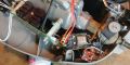
Loose placement of IOT Controller Add-On with optional Temp/Humidity sensor
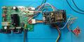
Controller with NodeMCU and Temp/Humidity attached
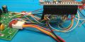
Front view of IOT Controller Add-On showing 15 pin header wiring
Rear view of IOT Controller Add-On showing power and thermistor connections
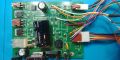
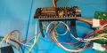
Placement of IOT Controller Add-On Wires


Basic Steps
- Thoroughly read the MM Defender Controller and MM Defender IOT Controller wiki pages.
- #Assemble Tools and Supplies
- #Test and Fix the Original Controller
- #Acquire Materials
- #Set up Development PC & Software
- #Program and Test Module(s)
- #Build the Wiring Harness
- #Modify the Controller PCB
- #Attach the Harness
- #Initial Test Outside Trap
- #Install Modified Controller into Trap
- #Move Trap to Operating Location
- #Final Test
- #Monitor from PC and Phone
Assemble Tools and Supplies
You will need the following tools, equipment, and supplies:
- 10x (opt. plus 50x) Stereo Microscope with illumination to clearly see what you are doing.
- Soldering iron with micro tip.
- Solder, solder flux, fine solder wick, PCB cleaner, alcohol, and brushes for cleaning.
- DeOxit or similar for cleaning switch and connector contacts.
- Micro tweezers for surface mount device (SMD) placement and manipulation.
- A medical syringe is helpful for prying and scraping.
- Volt-Ohm Meter (VOM) with suitable test leads.
- Clip leads for testing, plus a 1k or so resister to force the driver transistors.
- Oscilloscope, single or dual channel, calibrated, with probes. 10 MHz or higher. 1 MHz might work with allowances, not tested.
- Diagonal cutter and wire stripper for fine (e.g., 20-28) gauge wire.
Test and Fix the Original Controller
If the original controller is not working, or even if it is, it is a good idea to remove it, clean it, and inspect it thoroughly. The PCB is lightly (inadequately) sealed with a sealer for weatherproofing. Accordingly, you have to scrape off the sealant to probe a pad.
- Measure the resistances of the fan (?? Ohms), igniter (20 Ohms??), solenoid (?? Ohms), and thermistor (200 kOhms). If these are either too low or too high, they must be replaced. (?? what are the limits ??)
- Measure the resistance across C4. Disconnect the thermistor. Attach the VOM negative lead to the negative (ground) terminal of power supply filter cap C2 (large 3300 uF @ 25v) and the positive lead to J1 terminal 1. The resistance should be in the meg-Ohm range. If it is low (e.g., 20 kOhms), your controller is suffering from the "C4 PCB contamination" issue discussed on the controller wiki page. If low,
- Carefully unsolder C4 (ca 120 nf ceramic, was previously marked 150 nf). Remove the coating from the pcb in the vicinity of the pads. Thoroughly clean the PCB between the pads. Measure the resistance again until it is in the meg-Ohm range. Measure C4, then carefully strip and clean as necessary until infinite resistance is obtained. Build up a solder blob on each mounting pad. Solder C4 to the blog to allow space underneath for cleaning. Thoroughly clean and measure. When in the meg-Ohm range, seal the area with a PCB sealer. Use two coats.
- With the 'scope, measure the power supply voltages and ripple voltages. See that the ripples are symmetrical, and not too large for the D1 C2 +20v supply. The large bridge rectifier D2 has no filter cap, and will show all ripples. Attach the igniter and ground the J5 pin 2 lead to power the igniter, and see that the voltage does not just collapse. The RMS value should be appropriate for the 12 volts igniter. The igniter should light up, and be hot enough to ignite a propane torch. This also tests the power supply and long low voltage cord. If there is a problem with insufficient power, check the AC side of the supply to isolate the problem to the supply/cord or D2 rectifier bridge.
- Measure the +12 and +5v rails, they should be without ripple.
- Attach the fan, thermistor, switch, and gas valve solenoid. Power the unit again, and observe the low (ground) side of the Igniter, Fan, and Valve go from +12 to 0 volts as the driver transistors switch on. Check the switch LED to see that it flashes on power up.
If any of these tests fail, there is a problem with either the driver transistors, the controller, or the switch that must be fixed before the IOT Controller Add-On can be used.
- Check the switch terminal to see that it goes between +5v (off) and ground (on) when actuated. Make sure that wiggling the wires to the switch has no effect in either position.
- Use the 1 kOhm or so resister in series with a test lead connected to +5v rail (signal, supply voltage) to test the driver transistors. (You may have to scrape a pad on (e.g., on C7) and possibly solder a small piece of solid wire to access this rail.). Measure the voltage across the fan, igniter, and valve terminals to see that it goes on when the 1 kOhm signal is applied to the gate or base of the driver transistors. If not, the driver is defective, or possibly the igniter, fan, or valve solenoid is shorted.
If these tests are passed, perhaps you have fixed the problem, and can use your trap as is, provided the controller works. Try it. If working, catch some mosquitos and stop here. If not, you can continue with the IOT Controller Add-On.
Acquire Materials
- 1 or more ESP8266 ESP-12E NodeMCU modules, from any number of vendors, e.g., "MakerFocus ESP8266 NodeMCU LUA CP2102 ESP-12E Internet WiFi Development Board Serial Wireless Module." Cost about $12 for 2 (get 4).
- (optional) 1 or more HTU21D Temperature/Humidity module, e.g., "HiLetgo HTU21D Temperature Humidity Sensor Breakout Module I2C IIC 1.5V-3.6V." Cost about $7 for 2.
- 2 pieces of 40 pin female header strip, e.g., "10 Pcs 40 Pin 2.54mm Pitch Straight Single Row PCB Female Pin Headers." Cost about $6 for 10 pieces, a lifetime supply.
- Several colors of thin (28-32) gauge, stranded, flexible, very high quality hookup wire with high temperature PVC or Teflon insulation.
Set up Development PC & Software
- Connect the Expressive NodeMCU Module to the PC via USB
- If necessary, install the CP2102 Drivers to create a new COM port